Specifications
|
Cavity A
|
Cavity B
|
Cavity C
|
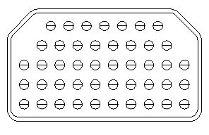
Connector Layout Arrangements
|
Polarizing Position
|
Performance Specifications
|
Material Specifications
Specifications
Part Number Note |
N/A Part number for reference only. Consult factory for actual part number. |
Connector Series |
N/A Amphenol ARINC 404 Filter Connectors |
ARINC Series |
N/A ARINC 404 |
Shell Style |
N/A Receptacle |
Termination Style |
N/A PC Tails |
Shell Size |
N/A Triple Bay, polarized |
Filter Circuit |
N/A
Pi
 |
Capacitance |
N/A 16000 to 32000 pF |
Plating |
N/A Olive Drab |
Mounting |
N/A
DG - 4 corners .210 mounting slots
 |
Custom Requirement |
N/A No |


Performance Specifications
Contact resistance Size 22: |
N/A 8.0 milliohms, initial (max.) 11.0 milliohms, conditioned (max.) |
Contact resistance Size 20: |
N/A 7.0 milliohms, initial (max.) 8.5 milliohms,conditioned (max.) |
Contact resistance Size 16: |
N/A 7.0 milliohms, initial (max.) 8.5 milliohms,conditioned (max.) |
Contact resistance Size 12: |
N/A 2.0 milliohms, initial (max.) 2.5 milliohms, conditioned (max.) |
Durability |
N/A 500 cycles min. - mating & unmating |
Temperature Range |
N/A -65°C (-86° F) to +125°C (+275° F) |
Vibration: |
N/A MIL-STD-1344, Method 2005.1, condition value E: random - 16.4G minimum severity: 8 hours in each of 3 mutually perpendicular planes with 100mA electrical load. No visible damage, breakage, cracking or loosening of parts and no discontinuities exceeding 1 microsecond. |
Shock |
N/A MIL-STD-1344, Method 2004.1, test condition A: Three shocks in each direction along each of 3 axes, mutually perpendicular to each other. No visible damage,breakage, cracking or loosening of parts and no discontinuities exceeding 1 microsecond. |
Working Voltage |
N/A 200 VDC |
Dielectric Withstanding Voltage |
N/A 500 VDC |
Insulation Resistance |
N/A 10 Gohm |
Current Ratings, Size 22 |
N/A 5 Amps |
Current Ratings, Size 20 |
N/A 7.5 Amps |
Current Ratings, Size 16 |
N/A 13 Amps |
Current Ratings, Size 12 |
N/A 23 Amps |
Filter RF Current Ratings |
N/A 3 Amps |
Insertion Loss, 0.1 MHz |
N/A - |
Insertion Loss, 1 MHz |
N/A 8 dB min. |
Insertion Loss, 10 MHz |
N/A 28 dB min. |
Insertion Loss, 100 MHz |
N/A 62 dB min. |
Insertion Loss, 1000 MHz |
N/A 68 dB min. |
Material Specifications
Shells |
N/A Aluminum alloy |
Retaining plates |
N/A Aluminum alloy per QQ-A-225/8 |
Polarizing keys |
N/A Aluminum alloy electroless nickel |
Insulator material |
N/A Glass filled plastic |
Inserts, grounded |
N/A Aluminum alloy per QQ-A-225/8 electroless nickel plated per MIL-C-26074 |
Screws, lockwashers, washers |
N/A Stainless steel - passivated |
Contact bodies |
N/A copper alloy gold plate |
Contact retention clips |
N/A Copper, gold plated per MIL-G-45204, Type II, Grade C, Class 1 |
Seals & grommets |
N/A Silicone/fluorosilicone elastomer blend per MIL-R-25988 |
O-Rings |
N/A Silicone/fluorosilicone rubber, colored blue |
EMI springs |
N/A Beryllium copper per QQ-C-533, electroless nickel plated per MIL-C-26074 |